Digital Video Forensics: “Is this video clip reliable?”

When we receive a request from an attorney or a forensic engineer to review digital video material, we are most often asked, “Is this video clip reliable?” Over the years, we’ve learned that this can mean many different things. The material in question is often a short piece of video in the form of a digital file that can be played using common media players, such as Windows Media Player. In some cases, the material is accompanied by proprietary viewer software that is required to view the video. On occasion, the video is actually in a DVD format, complete with title and menu.

But what our clients really want to know is one or more of the following:

“Is this video clip a true and complete copy of the original?”

“Has this video clip been altered or edited?”

“Can I rely on the time and date that appear in the video? To what degree of precision?”

“Are the proportions of the picture correct? Can I use it to measure distances?”

We generally deal with civil cases and not criminal investigations. In a criminal investigation, it is usually enough for investigators to obtain identification from the video. This may be facial identification of a perpetrator, the approximate height and weight of the individual, or simply a general description of the clothing the perpetrator was wearing. In some cases, investigators seek to identify a vehicle, by model, make, or color. The investigating agency may extract important images for enhancement or to distribute in aid to the investigation. But it is very rare that a criminal investigator concerns himself or herself with the precision of the date and time stamp, or whether a single frame may be missing from the video sequence.

In civil lawsuits, it is a different matter. Unsurprisingly (and according to the “CSI” shows), video recording systems are everywhere and frequently record video of incidents unintentionally. We have, for example, worked with numerous video files from security systems that recorded vehicle accidents in the background, a purpose for which they were not originally designed or installed. A civil lawsuit in connection with the accident might require the involvement of forensic engineers, who will normally perform a survey of the accident site to obtain accurate measurements of the positions of the vehicles before, during, and after the accident. Since vehicle speed may be a contributing factor in an accident, the engineers want to estimate the vehicle speed(s) at different locations. Speed is often estimated on the basis of skid marks or the amount of damage sustained by the vehicle(s), but the availability of recorded video gives the forensic engineer the opportunity to estimate vehicle speed by time interval. Knowing that speed=distance/elapsed time, and having accurately measured vehicle position during the investigation, all we need is a precise measure of the time interval between the frames of the video clip that show the vehicle at those measured positions. What could be simpler?

As it turns out, a lot. Most digital video recording systems were never intended to be used to measure time intervals to the precision required to differentiate between a vehicle going 45 MPH in a 45 MPH zone and a vehicle going 56 MPH in a 45 MPH zone. In fact, most date and time stamps inserted in video recording systems do not display with any more accuracy than one-second intervals, though some may display to a greater precision. If we do have a system with sufficient precision, there may then be the question of accuracy. Being precise to the millisecond is one thing. Being accurate is another. The task is further complicated if the video clip has been exported by the video recording system in a format different from that which was used in the original recording. It is very common for a video recording system that uses variable frame rate (i.e., the intervals between successive frames are not uniform) to export video clips to a video file format that uses a constant frame rate. The exported files are quite useful for identification purposes, but may useless for performing the calculations required to accurately estimate vehicle speed.

We frequently receive video clips in which the date and time stamp advances 15 minutes, or some other fixed time period, but the video clip actually plays in much less time using a software media player. We have several clips in which the audio portion of the file is shorter than the video itself, sometimes by more than 10%. The questions are then, “Which time intervals are correct? Can we state with confidence that the actual time interval between the vehicle at this location and that location is X.X seconds? What is our confidence interval for our estimate?”

Strangely, old-fashioned videocassette recorders are often more reliable and useful for the purpose of estimating time intervals than are modern digital video recording systems. A standard VHS recorder was designed to record video at 29.97 frames per second, and we have the further advantage of knowing that the camera was providing video to the recorder at an identical rate. Newer IP video cameras and digital recording systems normally work with variable frame rates and may even add the time stamp to the images only after they have been received at the recording unit, adding the problem of network latency to the mix.

A gentleman who was very experienced with digital video and had worked for years in the industry once told me that he would, “…never try to estimate time intervals in digital video with BOTH precision and accuracy.” While this might be an extreme view, it certainly reflects the challenges that face us.

We have attempted in this article to identify some of the important considerations in establishing the “reliability” of digital video used in forensic accident investigation. In subsequent articles, we will discuss some of these topics in more detail and introduce new topics of interest.

Posted in: Expert Witness, Security Technology, Video Forensics

Leave a Comment (0) →

Training Class – Preparing for the North Carolina SP-FA/LV Electrical Examination

Protective Resources is the premier provider of training for individuals who are planning to take the North Carolina Board of Examiners of Electrical Contractor SP-FA/LV examination. Our one-day class, “Preparing for the North Carolina SP-FA/LV Electrical Examination,” is a proven method for applicants to learn about the exam and to review the major topics it covers. We have classroom exercises that emphasize using the exam references, including many charts and tables, to derive the correct exam answers.

We are currently scheduled to present this class on the following schedule:

  • January 28, 2015                  ADI, Greensboro, NC
  • March 25, 2015                     ADI, Raleigh, NC
  • May 27, 2015                         ADI, Raleigh, NC
  • July 29, 2015                         ADI, Greensboro, NC

We are also happy to provide a quotation on presenting private class sessions for two or more students. If you are planning on sending two or more students to our regular class, it may be more economical to have us bring the class to you.  We are also able to offer coaching sessions, if you think you need more personalized help to ensure being successful.

Contact us at training@protectiveresources.com for more information.

Posted in: Training

Leave a Comment (0) →

Digital Video Forensics: Analog and IP Video Cameras

While time-lapse video recorders (TLR) using videocassettes remain in use in many smaller video surveillance systems, digital video recorders (DVR) and network video recorders (NVR) continue to be the preferred choice for larger and more complex systems. The video cameras that provide the images to these recording systems may be either analog or IP (internet protocol). For TLRs, analog cameras are almost invariably required, though it is technically possible to use IP cameras in a TLR system. For DVRs and NVRs, either analog or IP cameras, or a mixture of the two types, may be used. For the purpose of video forensics, knowing the type of camera that originally captured the video is critical to an understanding of several important aspects of the video material to be examined.

In North America, analog video cameras are almost certain to be compliant with the NTSC video system. (In other parts of the world, cameras may comply with PAL, SECAM, or other video system standards, which differ from NTSC in many crucial aspects. For the purpose of this discussion, we shall limit ourselves to the NTSC system.) The NTSC (National Television System Committee) standards for video systems were developed primarily to ensure the compatibility of broadcast television signals with consumer television sets.  The first standard was published in 1941, with subsequent revisions to accommodate advances such as color TV, and all of the standards are readily available from many sources for reference purposes.  The NTSC system standard is perhaps most important because it describes the way in which a video image is created on the “old-fashioned” CRT (cathode ray tube) television sets we used for well over 50 years. It should come as no surprise that analog video surveillance cameras of that period were designed and manufactured to provide a video picture that would display in an identical manner on video monitors using CRTs. Therefore, we can safely assume that an analog NTSC camera produces a signal that complies with the relevant sections of the NTSC standards.

Why is it important for a video forensics analyst to know if video material originated from an NTSC camera? Regardless of the method used to transmit and record the video images, the use of an analog NTSC camera places certain limitations and restrictions on the original video source and, consequently, on the recorded video images. We are frequently presented with digital video files that are known to have originated from an NTSC camera and, in many cases, can point to attributes of the video images that are inconsistent with an NTSC source. In some cases, there are anomalies that can be readily explained in no other way. In the following paragraphs, we will discuss a few of the most relevant features of the NTSC video system and the analog video cameras that employ it.

First, the aspect ratio of an NTSC video image is 1.33, or 4 units (wide) by 3 units (high). This aspect ratio is specified by the NTSC standards, but may vary slightly from system to system through minor variations in CRT scanning or other equipment variations. However, a DVR that produces a video file that is 720 pixels (wide) by 480 pixels (high) from an analog NTSC camera is either substantially distorting the image or cutting off portions of the image when recording since the aspect ratio of the digital video is 1.5 and definitely not 1.33. This is a common problem and once that we see in many cases.

Second, the standard frame rate for NTSC video is 29.97 frames per second. A new frame (complete image) is presented from the camera to the recorder every 33.4 milliseconds on a continuous basis. The consequences of this fixed, predictable frame rate can make a dramatic difference if the purpose of the analysis is to ascertain the exact time interval between any two frames in the digital video material. Since accurate and reliable time intervals are critical to establishing such basic data as the velocity of vehicles or other moving objects shown in the video, we are often asked to render an opinion on this specific aspect of the material. We will discuss this topic in more detail in a subsequent post. Ironically, “old-fashioned” videocassette recorders are often much better at providing accurate and reliable time interval measurements, as they were originally designed to record and play back video at precisely the same rate at which it was recorded (29.97 frames per second).

Third, NTSC video images are interlaced and each frame actually consists of two separate fields. A CRT monitor creates a visible image by scanning an electron beam horizontally across the inside face of the tube. The electron beam, guided by a strong magnetic field, starts at one side of the tube and scans to the other, then returns to the starting side and scans another line below the first.   This continues until the entire face of the tube has been scanned from top to bottom, creating a visible image. During the development of consumer television, it was discovered that creating an entire image every 33 milliseconds was not fast enough to prevent a noticeable and objectionable lag when objects in the image are moving. To compensate, the NTSC standards require that the electron beam scans the odd-numbered lines of an image and then returns to scan the even-numbered lines, thus requiring two complete scans of the screen to create what is a single interlaced frame. (Scanning just the odd or even-numbered lines is called a “field.” It takes two fields to create a frame. A single field takes approximately 16.7 milliseconds to create.) When a DVR or NVR records an analog camera, it must employ some technical method to convert the interlaced video signal to a digital video format, most of which are not interlaced. (A video image that is not interlaced is called “progressive.”) Some digital systems simply ignore one of the fields, recording just the odd or even-numbered field as if it was a complete frame. Other systems may combine both fields into a single progressive image. Each method creates slight anomalies that may have an impact on video analysis.

Fourth, NTSC video images are composed of discrete horizontal lines, but the horizontal lines themselves are continuously variable from side to side. A complete video image requires 525 horizontal lines to create (262.5 per field). Of these, only 483 lines are actually visible. The remainder are used for timing and control purposes and do not normally appear on the visible portion of the CRT screen. (Early closed captioning for broadcast television embedded the caption information in the non-visible lines.) Therefore, the maximum number of discrete picture elements in the vertical portion of an NTSC video image is limited to 483. Any other number of vertical elements is a result of interpolation by the recording device, or by omitting one of the fields (see paragraph above). The horizontal scan lines themselves do not have discrete elements. The intensity of the electron beam that scans the inside of the CRT varies continuously over a fixed range as it moves from one side to the other. (Other techniques are employed to render color.) Since the signal varies continuously, there is no standard number of picture elements specified by NTSC for the horizontal dimension. The ability of a specific camera or monitor to resolve in the horizontal dimension is normally measured by the number of vertical lines it can successfully display on the screen. Both video cameras and CRT monitors vary tremendously in the number of vertical lines they can produce or display. It is not at all unusual for a system to have cameras which are only capable of producing a video image of fewer than 360 vertical lines connected to high-quality CRT monitors that can display more than 525 vertical lines. Again, understanding and interpreting the implications of the way in which NTSC video images are created plays an important part when reviewing digital video material.

So far, we have discussed analog NTSC cameras exclusively. We will now turn our attention to IP video cameras.

Many consumers confuse digital video cameras with IP video cameras. Some analog NTSC video cameras use digital technology to capture and process video images, and these cameras can certainly be considered to be digital. However, the video is then converted to NTSC standards to be transmitted on coaxial cable, twisted pairs, or some other transmission media. The conversion to an NTSC signal necessarily means that the video is then subject to the NTSC requirements discussed in previous paragraphs. IP video cameras do not comply with NTSC standards, though some units may simultaneously provide both an IP and an NTSC output.

IP video cameras transmit video images to the recording device using the internet protocol. At the most basic level, this requires the image to be digitized (or “encoded”) and then converted into data packets that can be transmitted over a data network. The variety of methods for digitizing and transmitting video from a camera are far too numerous to describe in this paper, so we will limit ourselves to describing some of the key differences between IP cameras and NTSC cameras.

Unlike cameras that comply with NTSC standards, IP cameras are not required to provide video at a standard, uniform frame rate. (When dealing with digital video, many analysts prefer to use the terms “image rate” or “images per second,” rather than “frame rate” or “frames per second.” For the purposes of this paper and to make comparison easier, we will use the “frame” terminology for both types of camera.) There are two major reasons for this: First, most IP cameras can be programmed to provide individual frames either at specified intervals or upon request. This prevents overloading the data network by transmitting video data that are not needed or cannot be recorded by the system. Second, digitized video is often encoded using methods that permit variable frame rates. For example, many MPEG-4 encoding methods embed information on the presentation time of an individual image and the length of time that it should be shown on the display monitor. This is in sharp contrast to the NTSC system, where video frames are presented continuously and at fixed intervals. As a consequence, it can be extremely difficult to ascertain the actual time interval between two events (or frames) in a digitized video sequence unless we have extremely high confidence in both the camera and the recording system.

Another major difference between NTSC systems and IP systems is that the aspect ratio of the images may vary significantly depending on the equipment used and the recording settings. It is not unusual for an IP camera to transmit video images with one aspect ratio (for example, 1.5, or 720 pixels by 480 pixels) that is subsequently altered either in recording or when it is played back on a monitor. This is further complicated for both NTSC and IP cameras by the fact that individual pixels on NTSC monitors are of a slightly different shape than those found on most computer monitors. Ascertaining exactly what aspect ratio the original image had can be very challenging, but critical for measuring the velocity or position of moving objects.

Finally, the digitizing process that encodes the digital video at the camera can introduce some significant anomalies. Because of technical limitations and the desire to reduce bandwidth usage on the data network, many decisions have to be made about the acceptable frame rate, image size, and image quality for any individual IP camera. (This is also a major consideration when the video signal from an NTSC camera has been digitized for recording or transmission.) The encoding process that digitizes and compresses the video images necessarily introduces artifacts and anomalies into the images. Perhaps the best known and most easily recognized artifact is macroblocking, the appearance of block-like structures in some portions of the video image. But there are a number of other characteristics of the encoding process that can produce more subtle alterations in the image that are easily missed by the typical viewer.

This is not to say that IP video cameras are inferior to NTSC video cameras. One area in which IP video cameras excel is image resolution. It would not be possible, for example, to transmit video images with megapixel resolution using NTSC technology. As we have seen, there are hard limits on the number of horizontal lines in an NTSC signal and even economical IP video cameras far exceed these limits by producing images with two and three times this vertical resolution limit. There are excellent reasons for users to select video surveillance systems that use modern IP cameras.

We have attempted in this paper to identify some of the important characteristics that distinguish NTSC video cameras from IP video cameras and to describe the importance of identifying which type of camera was used to create a digital video file that is subject to analysis. In subsequent papers, we will discuss some of these topics in more detail and introduce new topics of interest.
Posted in: Video Forensics

Leave a Comment (0) →

Hacking Sony – Corporate culture broken from the top down

One of the questions I keep asking myself as I keep reading the dozens of recent articles about how Sony got hacked by “North Korea” is, why does Image left on screens for 2014 Sony HackSony KEEP getting hacked?

The short answer is “because they can”.  But the longer answer points to a corporate culture that doesn’t understand the need for protection of information assets, or the people who are constantly after those assets.

On November 24, Sony discovered that its corporate network had been hacked. The attackers took terabytes of data, deleted the original copies from Sony computers, and left messages threatening to release the information if Sony didn’t comply with the attackers’ demands.  But it was really much worse, not only was work disrupted as Sony’s IT professionals scrambled to recover lost data and restore data services, much of the proprietary information of Sony Corp. was released into the public domain for everyone to see.  Unreleased movies, private email conversations, celebrity contact information, social security numbers, passwords, and salary information were released into the wild.  The damage will be felt for years to come.

I’m uncertain of the actual number of cyber attacks on Sony (and only Sony knows the real number), but this latest attack has to put it somewhere in the high teens.  This attack was the latest of a string of attacks that has been happening since 2003, mostly related to Sony’s DRM policies and certain lawsuits over “hacking” the Sony PS3 platform.  At least, that’s where I think it all began.  Since then, it’s become the “hip” thing to do for black  hats, Hack Sony.  The notion that North Korea is behind this latest attack as claimed seems pretty thin to us, and also to the FBI in their official statements so far.

But what really is the cause of this?  From what I have read, it looks like it stems from a top down culture of a lack of respect for information security.   Their IT security department is woefully thin, understaffed for a company of Sony’s stature, security equipment and software was not properly installed, policies not enforced, and even simple things like compartmentalization of data, like keeping performer contracts or salary information separate from other data sources, were apparently not properly implemented.   This seems odd, since much of the technology Sony has developed (or bought) for DRM and copyright protection is fairly sophisticated, and expensive to develop.

Skipping the technical aspects of what Sony should have done or should now do to protect itself from cyber security, I will just propose in simple layman’s terms what a company in Sony’s position should consider across their corporate footprint.

  1. A top down philosophy of information security starting with corporate officers.
  2. Increased IT security staff and technology solutions to better identify, insulate and protect from cyber threats.
  3. Corporate wide training in information security, compartmentalization, best practices for data security and user authentication.
  4. Mandatory periodic password audits for all personnel (no Prima donnas who can’t remember a password).
  5. Two step authentication for most or all access, especially to sensitive information repositories.
  6. Regular security audits for physical and IT security.
  7. Personnel background checks, exit interviews with binding nondisclosure agreements.
  8. Active content filtering for incoming and outgoing internet traffic, strict VPN use for remote sites, and GEO IP security filtering at the desktop level.
  9. Active enforcement of corporate policies and legal prosecution for data breach events by employees or contractors.

Meanwhile, the media will be poring over mountains of sensitive information they shouldn’t have, hoping to find the next juicy bit of “Sony Dirt” to release in it’s next news cycle.


Posted in: Security Technology, Vulnerability Analysis

Leave a Comment (0) →

Do You Know Where Your Power Supply Is?

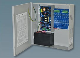
Altronix Eflow16 Low Voltage Power SupplyWe’ve all had it happen: either a bad battery or a blown fuse in a security power supply.   It causes cameras to fail, a card access door to stop working, or a whole panel to fail.

Power supplies in their simplest sense do a very basic thing:  They turn 120 volts AC power to low voltage DC power for low voltage security devices such as cameras, card readers, alarm panels, or detection devices.   And while they have become more sophisticated, adding fused outputs, relay contacts for fire alarm disconnects (life safety egress for maglocks), and smart battery chargers, until recently it was up to the security integrator or maintenance staff to maintain the power supply by testing power and replacing batteries periodically.

In the IT world, just about everything is monitored – Computer servers, network switches, server room air conditioning and filtration units, UPS battery backup systems, even cameras in the data closet monitoring temperature, humidity, and noise levels.  Much of this information is sent via the Simple Network Management Protocol (SNMP).  This protocol is monitored by software that notifies console operations of the exact conditions or problems that may arise with hardware or software in the footprint.

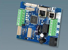
Enter the power supply network module.  The Altronix LINQ2 is a new product that offers the same kind of monitoring capability used in the computer industry.

The Altronix LINQ2 network module is designed to interface with eFlow and MaximalF power supply/chargers. It enables power supply status monitoring and control of two (2) eFlow power supply/chargers over a LAN/WAN or USB connection. LINQ2 provides values on demand for AC fault status, DC current and voltage, as well as Battery fault status and reports conditions via SNMP.

Now security operations can be notified of potential problems and critical failures as they happen, or maybe even before.

For more information visit http://www.altronix.com/products/product.php?name=LINQ2

Altronix linq2 SNMP module

The Altronix LINQ2 SNMP Network Module

Posted in: Fire and Life Safety, New Equipment and Gadgets, Security Technology

Leave a Comment (0) →

Layers – Not just for Onions and Ogres

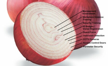
Security has been thought of and taught to others as a “layered approach” for centuries, and as such is not a new concept.   The Romans used layered concepts in their infantry tactics as well as their defensive fortifications.   With all due respect to “Shrek“, security is like an onion, and is a complex layer of countermeasures that make up a suite of hurdles that, presumably, are so confounding or problematic that the opponent gives up, gets caught, or never attempts anything in the first place.

The layers of security

Layers of security are a simple concept, but the concept is often overused by security professionals in discussion and even trivialized as not very important.  As Americans, we tend to rely very heavily on technology.  We understand technology, and we’re pretty good at it.   But while having thermal night vision cameras, fiber optic sensing cables, and CCTV drones flying over your campus are an impressive security posture, sometimes just a plain old chain link fence or dense thornbush hedge are enough to deter the would be criminal.  The most effective barrier I ever saw was a dense hedge of thorns called a  “living wall”.   It was 6 feet tall (and still growing), and you couldn’t climb it, cut it, or burn through it.

We once worked with a client that had installed a $4500.00 bullet proof door with a card access proximity reader installed behind Lexan (to protect it too) on the wall.  It we very impressive, until we learned that the wall it was installed  in was only sheetrock and metal studs, and you could kick through it and completely bypass the door.

Security layers mean from the outside in, with each layer adding to the increased security profile.   But security profiles are different for different companies, buildings, or campuses.  It depends upon the corporate philosophy, culture, and threat profile.  What may be reasonable for a chemical company manufacturing DOD explosives may not be suitable for a quarry.

Start with the outside, what are the threats from the street, the site perimeter, or even from the air?  Then work to the building perimeter, where are points of entry, access control weaknesses, or blind spots?  Internally you should look at the lobbies, common areas, break rooms, stairwells, and vestibules.  Then finally to policies and procedures relating to security, safety, and employee awareness.  Each of these areas will generate questions, to which you should generate answers in the forms of layers of security to add to your security profile.

Posted in: CPTED, Security Consulting

Leave a Comment (0) →

PINs Matter

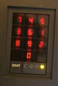
scramblepad

Hirsch Scramblepad

When working with a client once, they asked us to help harden their biological research labs by recommending additional security measures they could install. We did an initial and very casual walkthrough with them of the labs and how they were used. They were particularly proud of the Hirsch Scramblepads they had installed for access controlled doors. For those unfamiliar with these, they are an ingenious type of PIN pad where the numbers change each time you begin to enter your PIN sequence. This way, someone cannot peek merely at where your fingers were and assume that if you were at the bottom right of the pad, it was a 9. Anyway, they were (and still are in some circles) the Cadillac of PIN pads for access control.

As we began interviewing some of the lab staff, we asked how well they liked the keypads and how they were used. Most responded that they felt the keypads worked very well and were kind of “Star Wars” like because of their technology. We soon learned however, that the PINs used were 4 digit pins, and that there were a couple of hundred people who had access to these labs. To make it worse, departmental policy was that the individual was allowed to select their own PIN.  Yikes.

So, I promptly walked up to a PIN pad, and entered “1234”.

“Click”.  The door opened.

Okay, “1379”.  “Click”.

Yep.  Hmmm, one more, “2468”.  “Click”.   Okay, I see the biggest problem…

The good news, is it was a cheap fix.  That doesn’t mean easy, it was just cheap.  The long term fix was to add card access with CARD+PIN readers to enhance security; but in the mean time, we just increased the number of digits in the PIN, and assigned the PINs to the staff instead of letting them pick their own.  That’s why it wasn’t easy.  Some of the staff complained because now they had to learn a new PIN, and sometimes they forgot it, locking themselves out of the lab until they could remember it or get it reset.   Memorizing a new number (don’t we have enough numbers, passwords, etc. to learn already?!) is not fun and shouldn’t be necessary just to get into work.

Reading this now, this all probably seems like common sense to you, and it is.  It’s just that sometimes common sense isn’t used in practical applications the way we would always expect.  Security is a hassle, an inconvenience.  So, someone decided to make it easier on people and let them pick their own PIN.   This is were Security Policy and Procedures come into play.  They should be developed, implemented, maintained, and tested.  Had a proper policy been conceived and applied to the issuance of access control PINs, our job wouldn’t have been so easy.

PINs Matter

Just like passwords, a weak PIN is worse than NO PIN at all, because it gives you a false sense of security when there really is none.  If you still use only PINs, pick unique PIN of at least 8 digits, and ensure that they are unique for each user.  But better still, couple a PIN with an additional level of access control such as card access or biometrics.  After all, two levels of security are always better than one.


Posted in: Access Control, Security Technology

Leave a Comment (0) →

Analog to IP Camera Technology Migration

In a recent project, PR was contracted to assist a client in the migration of a multi-campus, traditional analog closed circuit TV system to a modern IP digital network based camera and recording system. This is a growing trend in the industry as clients realize the benefits not only increased camera resolution and recording capabilities, but also leveraging corporate infrastructure costs to reduce the overall total cost of ownership for their company.

It goes like this:

Traditional CCTV systems use analog NTSC (or PAL in some countries) cameras which connect via coaxial cable or fiber optic cable to an analog recording device, matrix switcher, and/or monitor. Sometimes the recorders are digital video recorders, but there are still alot of VCRs out there recording to plain old VHS tape. All of the equipment is still using or manipulating an analog video signal in some way.

The conversion requires new field devices, new infrastructure, new recording equipment, and new monitoring equipment. It can be expensive to install. However, the paybacks are big. With the advent of megapixel IP cameras, it is now possible to get very high resolution images that can be recorded and monitored anywhere your corporate network can go, and beyond. Factor in digital PTZ technology that allows for continuous monitoring of 360° from a single camera in high resolution, and you can now replace multiple cameras with only one. There are some limitations however, as outdoor PTZ cameras in parking lots or on poles aren’t necessarily good applications for IP PTZ cameras just yet. But eventually technology will catch up.

Hybrid compromises are available too, where analog cameras can be converted to IP encoded H.264 streams and sent to network video recorders (NVR) which record network video streams. The resolution is only as good as the analog camera (usually no more than about 500 lines, or 704 x 480 resolution). This pales in comparison to 1080p cameras or even higher resolution megapixel cameras on the market today, but it is a good way to leverage some legacy hardware with new recording and transmission technology.

The biggest advantage of digital IP video is the flexibility it affords. Need to move a video stream to a different recorder? Just change the IP settings. Need to monitor the video in multiple locations? Just pull down multiple streams from different PC workstations. Need to move the monitoring to a remote location or disaster recovery site? No problem, just connected to the video servers from the alternate location. All of these features were MUCH more difficult with legacy analog video.

In short, digital IP camera technology affords a suite of new and enhanced features that give security operations response and investigation tools that previously were nonexistent or too expensive to implement. There is a cost to this technology, but the power and flexibility is well worth the price.

Posted in: Security Technology

Leave a Comment (0) →

PR Invited to Participate in State and Local Fire Marshal Policy Meeting

Meeting with North Carolina state and local fire marshals, Protective Resources has been invited to participate in a discussion of how the State and local code officials are going to be educated/trained in the new requirements for fire alarm system communications to comply with the 2010 and 2013 Fire Alarm Code. These new requirements are complex and will require the code officials to have a better understanding of data networks, Internet Service Providers, and Voice Over IP communication services.

Posted in: Company News

Leave a Comment (0) →
Page 5 of 5 12345